To read an aluminium flat bar drawing, check the part number and revision first, then the units, finished dimensions, measurement references and order notes. Before approving a quote, make sure the supplier is pricing the same material, holes, finish and inspection requirements shown on that drawing.
This guide is for buyers ordering cut or drilled aluminium flat bar, also called aluminum flat bar. You do not need to understand every engineering symbol to spot an incomplete order. Start by asking: What size is the finished part, where do measurements start, and what variation is allowed?
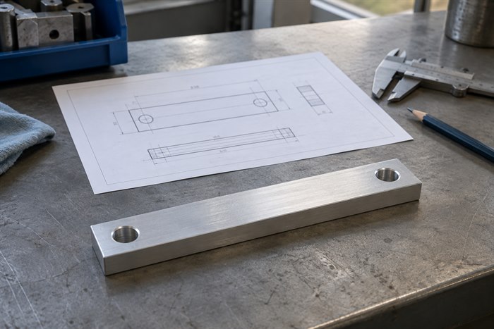
Size tells you whether the bar fits the space. Hole positions tell you whether it lines up with the assembly. Notes tell you what work and checks the order includes. Read all three before comparing prices.
1. Check the drawing identity before the dimensions
The information box, often called the title block, identifies the part and its version. Match the drawing number and revision on the quotation and purchase order. A changed hole position can matter even when the overall bar size stays the same.
Units
Look for millimetres or inches. Do not infer units from the apparent size of a printed drawing.
Material
Check both the alloy and its condition, called the temper. “Aluminium” alone does not fully identify the material.
Finished condition
Confirm whether the dimensions apply before or after machining and any coating. This matters where parts must fit together.
Use the stated dimensions, not a ruler on the printout. For general size notation, see our aluminium flat bar sizes and specifications guide.
2. Read an aluminium flat bar drawing with an example
Imagine a mounting strip measuring 50 × 10 × 300 mm: width × thickness × length. It has two holes, each 9 mm in diameter, passing through the full thickness. The following original illustration uses assumed dimensions to explain reading order.
| Drawing information | Plain-English meaning | Buyer’s check |
|---|---|---|
| 50 × 10 × 300 mm | 50 wide, 10 thick, 300 long. | Use this same order in the enquiry. |
| 2 × Ø9 THRU | Two 9 mm diameter holes through the bar. | Do not confuse hole diameter with distance between holes. |
| 30 and 270 from C | Both hole centres are located from the left end. | The second hole is not 270 mm from the first. |
| 25 from B | Both centres are 25 mm from the lower long edge. | Measure to each hole’s centre, not its rim. |
The nominal centre-to-centre spacing is 270 − 30 = 240 mm. This is a calculation from the example, not an additional acceptance requirement. Actual permitted variation must come from the approved drawing.
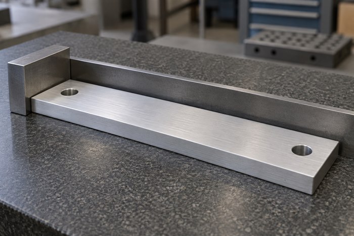
3. What is a datum? Think “the agreed reference”
A datum is an ideal reference point, line or plane used to locate or orient features. It is established from a specified physical feature, such as a face of the bar. KEYENCE’s datum guide explains this distinction.
For our example, imagine resting the strip on face A, aligning its long side B, and locating its left end C. This gives buyer and supplier a shared way to describe the holes. On a formal drawing, follow the actual datum symbols and reference order; A, B and C do not always mean these particular faces.
Ask this before approving: “Are both hole locations measured from the same end and edge shown on the drawing?” If one person starts at the opposite end, matching numbers may describe different positions.
4. Read the allowed variation, not just the target size
A tolerance states the permitted variation. For example, an assumed length requirement of 300 ±0.5 mm gives limits of 299.5 to 300.5 mm. These are teaching values, not a recommended tolerance or a supplier capability claim.
Where no tolerance appears beside a dimension, check the general tolerance note. Do not assume the requirement is zero variation or choose a limit yourself. The National Physical Laboratory’s drawing guide explains general tolerances and their connection to measurement.
Also separate hole size from hole location: a correctly sized hole can still be in the wrong place. Ask the designer to identify which requirements control assembly fit. Requesting tighter limits everywhere may add work without improving the parts that matter.
Formal symbols follow the drawing’s declared standard. ASME Y14.5 defines rules for dimensioning and geometric tolerancing. Ask for clarification when a symbol is unclear; do not replace it with an assumed “±” value.
5. Turn drawing notes into a clear order
Read the notes as part of the specification. Before accepting a quote, check these five items against the drawing:
- Material: the same alloy and temper, with any proposed substitution identified for approval.
- Work included: cutting only, or cutting plus drilling and other agreed operations.
- Edges and finish: the required burr removal, corner treatment and surface condition.
- Inspection: which dimensions need recorded results and how they will be checked.
- Delivery: quantity, part identification and protection for surfaces that matter.
“Please quote 200 mounting strips to drawing FB-018, revision B. Finished size: 50 × 10 × 300 mm, width × thickness × length. Include the two through holes, material, tolerances and edge treatment specified on the attached drawing. List any exceptions separately before order approval. Please confirm the inspection records included.”
This is a hypothetical enquiry. Replace its part number, revision, quantity and dimensions, then attach your complete drawing. If it specifies 6061-T6, our 6061-T6 flat bar product page is a relevant starting point for the material discussion.
Questions buyers often ask
Can I send a sketch instead of a CAD file?
A clear sketch can start an enquiry. Include units, views, dimensions and the intended use. Before production, agree a controlled drawing with a part number, revision and complete requirements so both sides work from the same information.
What if the quotation and drawing disagree?
Request a corrected quotation or an explicitly approved drawing change. Record which document governs each requirement. Do not assume that a short product description includes every operation shown in the drawing.
Does this drawing also specify an electrical busbar?
It explains geometry only. A current-carrying part also needs an approved electrical specification, including material and connection requirements. A bar that fits the available space is not automatically suitable for the electrical duty.
Prepare your drawing for an enquiry
Send the drawing number and revision, application, quantity and delivery destination. Highlight any unclear notes or critical fit requirements, and ask for written confirmation of the proposed supply scope.
Discuss your drawing and order requirements →Technical references
KEYENCE — What Are Datums? Reference geometry and physical datum features.
National Physical Laboratory — Good Practice Guide No. 79 (2005) Background on drawing interpretation and measurement; not a substitute for the standard specified on your drawing.
ASME — Y14.5-2018 (R2024), Dimensioning and Tolerancing Public scope description. No claim of conformity is made for the teaching illustration.